One dead station with a normally powered controller is an isolated circuit problem. Confirm the station has runtime, inspect its terminal and any expansion module, then determine whether the controller sends the command and whether it reaches the valve. Do not replace the entire controller before separating its output from the field circuit.
Match the pattern before opening anything
| Possible cause | Best clue | First check |
|---|---|---|
| Zero runtime or wrong program | Station works manually but not in schedule | Review every active program |
| Loose terminal or module | Failure followed controller work | Power off and inspect seating |
| Failed station output | No command at one terminal | Have output compared with a known-good terminal |
| Field wire or valve circuit | Controller output is present but valve is silent | Inspect valve-box splice and solenoid |
Read the system before replacing a part
Use the observation that most closely matches your yard. Each row changes the next test, so you do not spend an afternoon proving the wrong theory.
What it meansScheduling is not the main boundary.
Do nextCompare its terminal output with a working station.
What it meansThe hardware path works.
Do nextCheck station runtime, program assignment, days, and sensor state.
What it meansThe loss lies in field wire, splice, common, or solenoid.
Do nextRepeat the live comparison at the valve box.
What it meansThe field circuit can work.
Do nextThe original output or module is suspect; restore wiring after the controlled test.
Four tests that narrow the fault
Stop as soon as one result gives you a clear boundary. The goal is not to perform every test; it is to eliminate whole groups of causes safely.
- 01
Run the exact station manually
Use controller manual-station mode, not the valve bleed, and watch the station number.
IF YES / NORMALIf it waters, diagnose automatic programming only.
IF NO / ABNORMALIf it stays dry, continue through output, wire, splice, and valve.
- 02
Compare active terminal voltage
A trained person measures station-to-COM on a working station and the failed station while each is active.
IF YES / NORMALSimilar output moves the fault downstream.
IF NO / ABNORMALOnly the failed terminal lacks output: controller terminal or module is the boundary.
- 03
Compare at the valve splice
Measure across the failed station conductor and common at the valve during its manual run.
IF YES / NORMALExpected voltage at the valve points to solenoid or valve mechanics.
IF NO / ABNORMALOutput at controller but not valve proves loss in cable or connection.
- 04
Prove the water path
Use the valve's approved manual bleed with the irrigation supply available.
IF YES / NORMALNormal spray confirms the lateral pipe and heads.
IF NO / ABNORMALA hydraulic fault coexists; do not blame the controller alone.
Numbers worth measuring
Compare like-for-like while the station is commanded on; model specifications control.
Common fixes that waste time
A reset destroys evidence and may create a second problem.
The bleed bypasses the entire electrical path.
A temporary comparison is not a safe permanent repair and can mislabel zones.
How the evidence changes the repair
Station 5 failed from both the schedule and controller manual mode; station 4 worked.
- Station 5 produced 26 VAC at the controller.
- Only 2 VAC reached its valve-box splice.
- The valve opened normally from the bleed screw.
The controller and hydraulic path both passed. Voltage disappeared between them, so the field connection—not the valve—was the actionable boundary.
How to confirm the repair actually held
A single successful start can hide an intermittent splice, sticky valve, remaining leak, or scheduling problem. Recreate the original conditions before calling the job finished.
Pass: The valve opens on every command.
If not: An intermittent output, splice, wire, or solenoid remains.
Pass: Automatic and manual operation agree.
If not: Programming is a second, separate fault.
Pass: Opening delay and spray strength are similar.
If not: The electrical fix may have exposed a hydraulic restriction.
Check these in order
- 01
Run the station manually from the controller
If it works manually, the field circuit is capable and the problem is programming or sensor logic. If it fails manually, continue with terminal and field checks.
- 02
Review runtime in each program
A station can have zero minutes in Program A while being configured elsewhere. Check active programs, water days, seasonal adjustment, and any smart-controller zone disable setting.
- 03
Inspect the station terminal
Disconnect controller power before reseating loose copper or checking a plug-in expansion module. Keep the station label matched to the correct field wire.
- 04
Compare output professionally
A trained technician can compare the suspect station with a known-good terminal during manual operation. No output suggests controller or module trouble; normal output moves the fault into the field circuit.
- 05
Trace the zone circuit
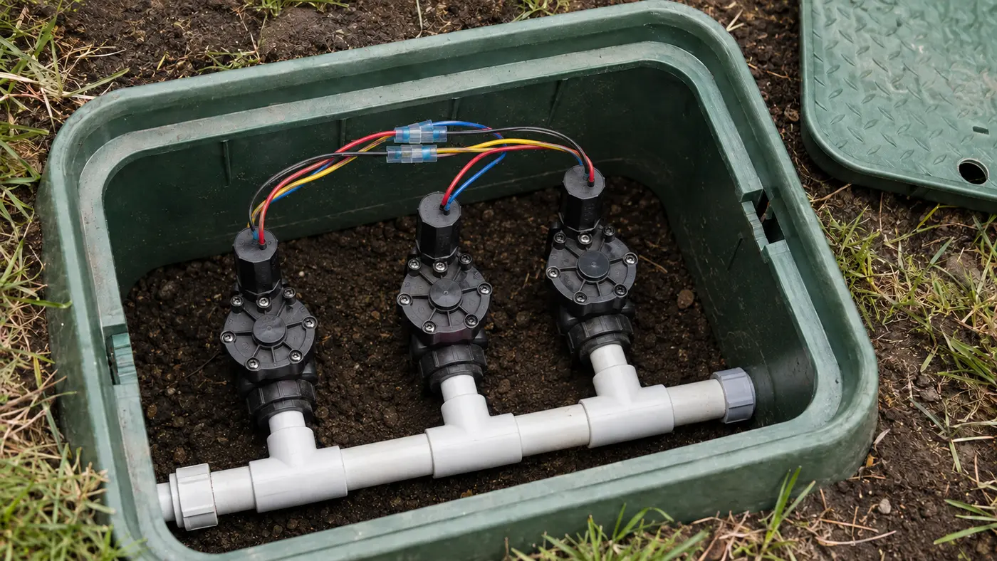
At the valve box, inspect the station splice, common splice, and solenoid. A working valve by manual bleed confirms the hydraulic side and narrows the fault to electrical control.
- The controller module or terminal requires live measurement.
- The field wire is open underground.
- Moving wires between terminals would defeat pump or master-valve logic.
What homeowners ask about this symptom
Is a station the same as a sprinkler zone?
In most residential controllers, a station output controls one zone valve, so the terms are often used interchangeably. The station is the controller circuit; the zone is the hydraulic area it operates.
Can I move the wire to another station terminal?
A qualified person may use a known compatible spare terminal as a diagnostic, but programming, module limits, pump logic, and labeling must be preserved. Do not improvise on an unfamiliar controller.
Sources and review notes
General maintenance logic is checked against EPA WaterSense outdoor irrigation guidance. Product controls and disassembly steps vary by model; use the current manufacturer manual for your exact valve, controller, or sprinkler head.
Published and last reviewed: August 28, 2026