When every zone fails at the same time, separate a controller problem from a shared water-path problem. Confirm the controller is powered, test two zones manually, verify the known irrigation supply is open, and check any rain sensor, common wire, master valve, or pump relay that all zones share.
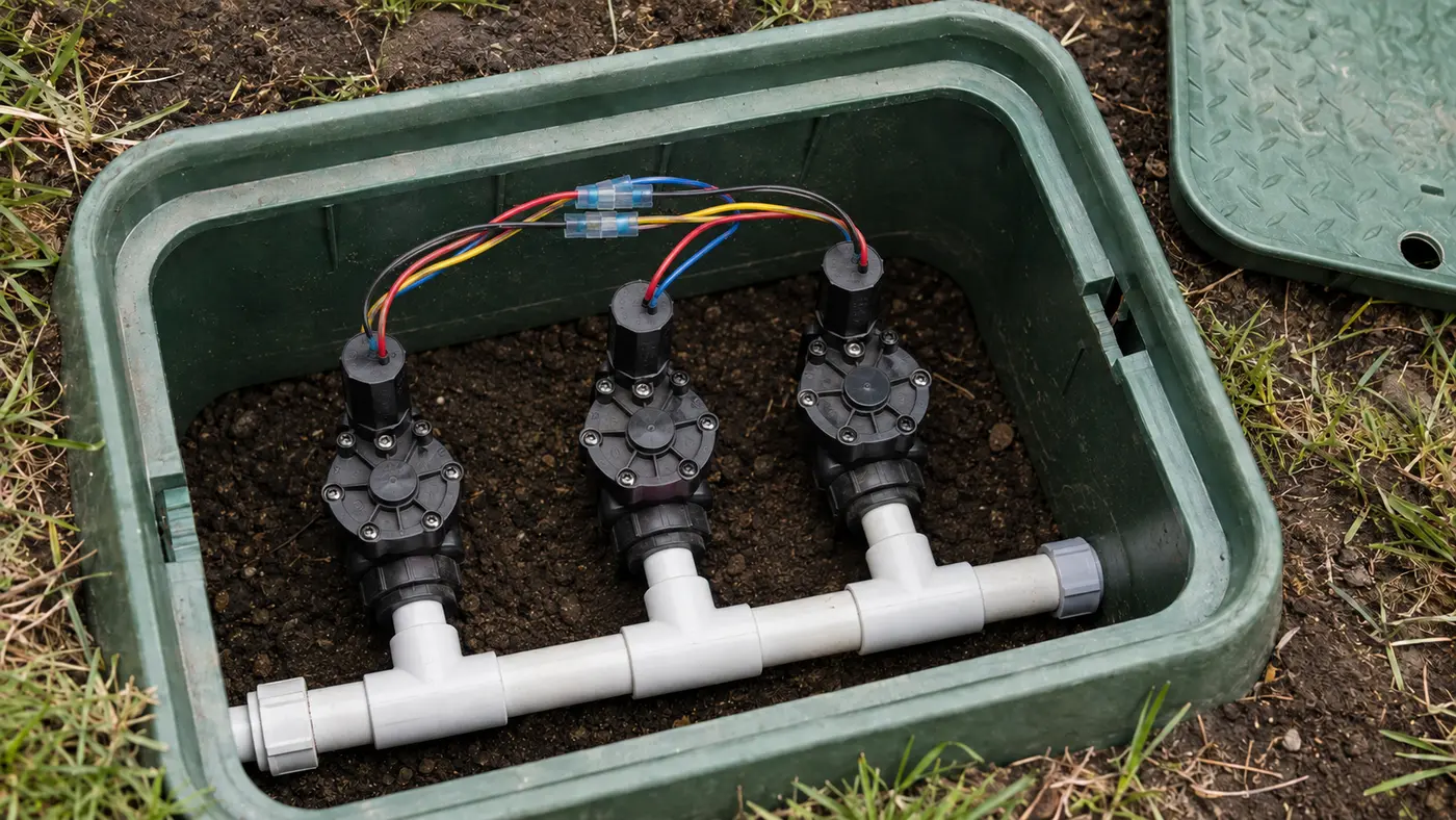
Match the pattern before opening anything
| Possible cause | Best clue | First check |
|---|---|---|
| Irrigation water shut off | Valves are silent or click but no zone flows | Verify the dedicated irrigation shutoff is open |
| Controller or transformer power loss | Display is blank or resets | Check the outlet, breaker, and plug-in transformer |
| Common-wire failure | Controller runs but several valves stay silent | Inspect the common terminal and shared field splices |
| Master valve or pump fault | Individual zone commands appear normal | Look for a wire on the P/MV terminal |
Read the system before replacing a part
Use the observation that most closely matches your yard. Each row changes the next test, so you do not spend an afternoon proving the wrong theory.
What it meansThe controller has lost its low-voltage supply or failed internally.
Do nextProve the outlet first; do not open a hardwired enclosure.
What it meansA common wire, master-valve command, or controller output is missing.
Do nextLook for a P/MV wire and inspect the controller common terminal.
What it meansCommands reach the field, so a shared hydraulic supply is more likely.
Do nextVerify the known irrigation shutoff and any master valve or pump.
What it meansThe shared water path works; remain on the electrical side.
Do nextCompare station-to-common voltage and inspect shared splices.
What resolved repairs add to this diagnosis
We matched 21 of the 100 reviewed outcomes to this symptom family. This is a convenience sample, not a universal failure-rate estimate, but every included case reports what restored operation.
When several or every zone failed together, the reported fixes repeatedly landed on something shared: common wiring, controller setup, a master valve, the supply path, or the controller itself.
Do not diagnose multiple valves independently until one manual valve-opening test and one shared-boundary check rule out common, master-valve, and supply failures.
A second manual shutoff, hidden under grass beside the meter box, was found and opened.
C30 · reported resolutionSeven of ten Rachio zones quit while three nearby zones still workedContinuity tests localized an open common between valve groups; a temporary bypass conductor restored all seven zones.
C59 · reported resolutionNo zones worked after backflow replacementA second buried master valve was discovered under shrubs; repairing its diaphragm restored flow.
C73 · reported resolutionThe controller showed normal output after lightning, but no valves openedRunning a new control conductor from the first valve box back to the controller restored current flow to all stations.
Four tests that narrow the fault
Stop as soon as one result gives you a clear boundary. The goal is not to perform every test; it is to eliminate whole groups of causes safely.
- 01
Compare two unrelated stations
Start one nearby and one distant station from manual controller mode.
IF YES / NORMALA single failure is not a whole-system fault; use the one-zone guide.
IF NO / ABNORMALTwo unrelated failures justify testing shared power, common, supply, master valve, or pump.
- 02
Separate display power from valve power
Confirm the display is stable, then observe whether a valve clicks during an active countdown.
IF YES / NORMALA click proves at least part of the 24-V command path is alive.
IF NO / ABNORMALA normal display with silent valves does not prove the valve circuit or common wire.
- 03
Open one known valve manually
Use only the manufacturer's bleed method; a master valve may also require approved manual opening.
IF YES / NORMALNormal water flow proves the downstream hydraulic path.
IF NO / ABNORMALNo flow moves the fault upstream to shutoff, backflow path, master valve, or pump.
- 04
Inspect shared connections
With controller power off, inspect COM, P/MV, and the earliest accessible common-wire splice for loose or corroded copper.
IF YES / NORMALSound shared connections move the diagnosis to output voltage or supply hardware.
IF NO / ABNORMALA failed shared splice can explain every silent valve downstream.
Common fixes that waste time
Independent coils rarely fail simultaneously; grouped failure is evidence of a shared dependency.
It shows controller logic, not water pressure or voltage at a field valve.
Misoperation can create a water-safety or flooding problem; identify the irrigation shutoff instead.
How the evidence changes the repair
Six zones showed normal countdowns but all stayed dry after valve-box work.
- Two valves opened normally with their approved bleed screws.
- Neither valve clicked from the controller.
- The first shared white-wire splice separated with light handling and showed dark copper.
Manual flow ruled out the supply. The grouped electrical silence and failed shared splice isolated the common return; replacing individual valves would not have changed the symptom.
How to confirm the repair actually held
A single successful start can hide an intermittent splice, sticky valve, remaining leak, or scheduling problem. Recreate the original conditions before calling the job finished.
Pass: Both open and produce normal flow, proving the shared path is restored.
If not: Record whether the missing event is command, valve response, or water; the shared fault is not fully isolated.
Pass: The program begins without a manual override and each selected station advances.
If not: A schedule, sensor, or delay problem remains after the hardware repair.
Pass: Connections remain dry and secure.
If not: Remake the connection with direct-bury waterproof connectors.
Check these in order
- 01
Test two unrelated zones
Start two stations manually from the controller. If neither produces water, do not replace two solenoids; the probability is much higher that a shared component has failed.
- 02
Check power and controller status
Confirm the display is stable and look for rain delay, sensor-off, seasonal-off, fuse, or fault messages. Use the exact model manual because bypass controls differ.
- 03
Verify the known water path
Check only shutoffs you can positively identify as irrigation controls. Do not force an old valve handle or dismantle a backflow preventer under pressure.
- 04
Identify shared electrical hardware
A common wire joins multiple valve solenoids. A master valve or pump relay may be controlled from the P/MV terminal. Loose shared connections can stop every station while the display still looks normal.
- 05
Escalate the right fault
If manual valve operation produces water, the supply path is available and the problem is electrical. If no valve operates manually, focus on the shared water supply, master valve, or pump.
- The controller or transformer shows heat, arcing, or water damage.
- A pump, pressure tank, master valve, or backflow device is involved.
- You cannot identify the irrigation shutoff safely.
What homeowners ask about this symptom
Can one bad solenoid stop every zone?
Usually no. One solenoid normally affects one valve. Every zone failing together points first to a shared supply, common wire, controller power, master valve, or pump relay.
Why does the controller look normal when no zones run?
The display confirms the controller has logic power, not that water is available or that the 24-volt valve circuit, common wire, master valve, or pump is operating.
Sources and review notes
General maintenance logic is checked against EPA WaterSense outdoor irrigation guidance. Product controls and disassembly steps vary by model; use the current manufacturer manual for your exact valve, controller, or sprinkler head.
Published and last reviewed: August 30, 2026