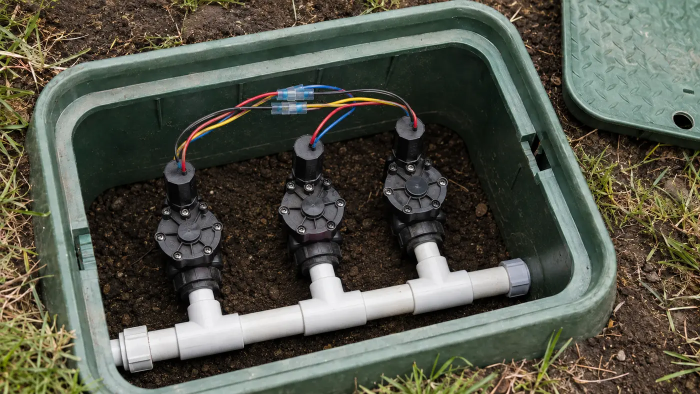
The common wire completes the circuit for multiple valve solenoids. A loose, corroded, or broken common connection can stop all zones or every zone downstream of one valve box while individual station wires remain intact. Group the failed zones by location and inspect shared splices with controller power off.
Match the pattern before opening anything
| Possible cause | Best clue | First check |
|---|---|---|
| Loose controller common terminal | All field valves fail together | Power off and inspect the C terminal |
| Corroded shared valve-box splice | Several nearby zones fail after rain | Inspect the common bundle in that box |
| Broken underground conductor | Downstream group fails with clean splices | Map the last working and first failed box |
| Multiple common paths or master valve | Failure pattern is inconsistent | Review the as-built wiring and P/MV circuit |
Read the system before replacing a part
Use the observation that most closely matches your yard. Each row changes the next test, so you do not spend an afternoon proving the wrong theory.
What it meansThey may share one downstream common-wire splice.
Do nextFind the last working and first failed valve box.
What it meansThe break likely lies after the working branch point.
Do nextInspect the common splice at that transition before tracing buried cable.
What it meansA marginal splice may become conductive or resistive when wet.
Do nextInspect for non-waterproof connectors and darkened copper.
What it meansWater and local valve mechanics are available.
Do nextRemain on the shared electrical return path.
Four tests that narrow the fault
Stop as soon as one result gives you a clear boundary. The goal is not to perform every test; it is to eliminate whole groups of causes safely.
- 01
Map the failure boundary
List working and failed stations and their valve-box locations before disturbing wiring.
IF YES / NORMALA geographic cluster creates a small search area.
IF NO / ABNORMALScattered failures may involve more than one issue or a controller module.
- 02
Inspect the COM terminal
Turn controller power off and verify the common conductor is secure and its copper is sound.
IF YES / NORMALA sound terminal moves the search to field branches.
IF NO / ABNORMALRepair the termination before opening valve boxes.
- 03
Compare voltage using the local common
A trained person measures failed station-to-COM at the controller and then at an accessible valve splice.
IF YES / NORMALNormal field voltage weakens the common-wire theory for that valve.
IF NO / ABNORMALController output that disappears in the field supports an open or high-resistance path.
- 04
Inspect the transition splice
With power off, open only the box between the last working and first failed branch and inspect waterproof connections.
IF YES / NORMALSound copper means tracing may be required.
IF NO / ABNORMALCorrosion or a loose multi-wire splice explains the downstream group.
Numbers worth measuring
The wire is often white, but function—not color—must identify it.
Common fixes that waste time
Installers can use any color; confirm its controller terminal and connections.
The last-working/first-failed boundary often exposes an accessible splice failure.
Valve boxes are wet environments; use properly sized direct-bury waterproof connectors.
How the evidence changes the repair
Zones 1–2 worked, while zones 3–6 became silent after a wet week.
- All four failed valves opened manually.
- The controller produced station voltage for each.
- The shared common splice in the zone-2 box contained water and corroded copper.
The ordered failure map located the branch point. One shared return repair restored four zones without four solenoids or a new controller.
How to confirm the repair actually held
A single successful start can hide an intermittent splice, sticky valve, remaining leak, or scheduling problem. Recreate the original conditions before calling the job finished.
Pass: Both respond repeatedly.
If not: The actual common-wire break lies elsewhere or more than one splice is damaged.
Pass: Operation does not change with wire position.
If not: Copper or connector contact remains marginal.
Pass: Moisture does not recreate the grouped failure.
If not: Use a correctly sized direct-bury connector and sound copper.
Check these in order
- 01
Map which zones failed
Write down every working and failed station and where its valve is located. A geographic cluster often reveals the shared splice or cable segment.
- 02
Inspect the controller common terminal
Disconnect controller power. Confirm that the common conductor is fully seated, not corroded, and not sharing a loose terminal with an unlabelled wire.
- 03
Open the nearest shared valve box
Look for a bundle connecting one common conductor to several solenoids. Replace wet, corroded, or loose connections with irrigation-rated waterproof connectors while preserving the wiring map.
- 04
Separate common from station faults
One failed valve usually indicates its station wire or solenoid. Several valves sharing a box or cable route failing together strongly favors a common-path problem.
- 05
Locate underground breaks professionally
If accessible splices are sound, a technician can use irrigation wire-locating and fault-testing equipment. Random digging often creates more damage and misses the actual break.
- The fault is underground beyond accessible valve boxes.
- The system has multiple controllers, decoders, pumps, or master valves.
- Live circuit testing or specialized wire locating is required.
What homeowners ask about this symptom
What color is the sprinkler common wire?
White is common in many installations, but color is not guaranteed. Trace labels and actual connections; never identify a wire by color alone.
Can one bad common splice stop only one zone?
Yes, if that zone branches separately from the splice. More often, a shared splice affects several valves connected downstream, which is why mapping the failed zones matters.
Sources and review notes
General maintenance logic is checked against EPA WaterSense outdoor irrigation guidance. Product controls and disassembly steps vary by model; use the current manufacturer manual for your exact valve, controller, or sprinkler head.
Published and last reviewed: August 28, 2026