When every other zone works, the main water supply and controller power are probably fine. The fault is usually isolated to that zone: its terminal, field wire, splice, solenoid, or valve diaphragm.
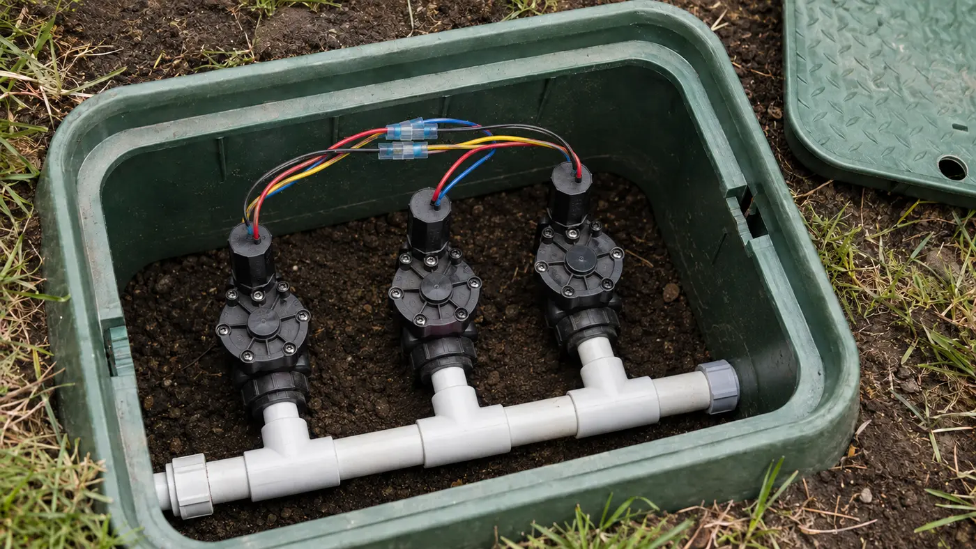
Match the pattern before opening anything
| Possible cause | Best clue | First check |
|---|---|---|
| Programming or terminal issue | The controller skips only this station | Run the station manually and inspect its terminal |
| Open wire or corroded splice | No click is heard at the valve | Inspect waterproof connectors in the valve box |
| Failed solenoid | Other stations operate normally | Test coil resistance with power off |
| Stuck valve diaphragm | Solenoid clicks, but no water flows | Try the manual bleed and check flow control |
Read the system before replacing a part
Use the observation that most closely matches your yard. Each row changes the next test, so you do not spend an afternoon proving the wrong theory.
What it meansWater reaches the valve and the diaphragm can pass flow.
Do nextStay on the electrical path: terminal, field wire, splice, and solenoid.
What it meansA command likely reaches the solenoid, but click alone does not prove the valve opened.
Do nextCheck flow control, supply to that manifold, and the valve diaphragm or ports.
What it meansThe failure starts at the controller output or module.
Do nextCompare the failed terminal with a working station during a manual run.
What it meansThe voltage is being lost in the field cable or a splice.
Do nextRepair accessible waterproof connections before tracing buried wire.
What resolved repairs add to this diagnosis
We matched 17 of the 100 reviewed outcomes to this symptom family. This is a convenience sample, not a universal failure-rate estimate, but every included case reports what restored operation.
The matching repairs did not support a replace-the-head-first approach. Most resolutions occurred at the station circuit, solenoid, splice, or valve; local nozzle trouble was the minority pattern.
First prove whether the valve opens manually. That single result separates the water path from the station electrical path before you buy a part or dig.
Cutting back and remaking the common-wire connections restored all zones.
C24 · reported resolutionA zone stopped after a contractor installed a new sprinkler headA wire locator found that the installer had cut the buried control cable; repairing that cut restored the zone.
C77 · reported resolutionA valve clicked electrically but would not pass waterInspection found a malformed, partly blocked solenoid air passage; replacing that component restored opening.
C87 · reported resolutionA zone lost pressure after two heads were cappedMoving new valve internals into the existing body restored stronger-than-before pressure.
Four tests that narrow the fault
Stop as soon as one result gives you a clear boundary. The goal is not to perform every test; it is to eliminate whole groups of causes safely.
- 01
Run a two-zone comparison
Run a known-good zone for two minutes, then the failed zone from the same manual-control screen.
IF YES / NORMALOnly one failure keeps the diagnosis inside that station circuit.
IF NO / ABNORMALIf both fail, switch to shared supply, common wire, master valve, or pump diagnosis.
- 02
Open the valve manually
Use only the valve maker's bleed screw or approved solenoid turn. If a master valve exists, it may also need to be opened.
IF YES / NORMALNormal spray proves the lateral pipe and heads can operate.
IF NO / ABNORMALNo water moves the fault toward supply, flow control, clogged ports, or the valve body.
- 03
Compare terminal voltage
With a trained person using AC volts, measure station-to-COM on a working terminal and the failed terminal while each is active.
IF YES / NORMALAbout 24–28 VAC on the failed terminal moves the test downstream.
IF NO / ABNORMALA good station has voltage but the failed station does not: controller terminal or module is suspect.
- 04
Repeat the test at the valve
Measure across the station and common conductors at the valve splice while the station is running.
IF YES / NORMALCorrect voltage at the valve points to the solenoid or valve mechanism.
IF NO / ABNORMALCorrect controller output but missing valve-box voltage identifies cable or splice loss.
Numbers worth measuring
Measure station-to-COM while that station is actively running.
Model-specific values vary; isolate power and compare with the exact manufacturer specification.
Common fixes that waste time
Working stations already prove most shared controller functions are alive.
One manual test can separate the buried hydraulic path from the electrical circuit.
Moisture returns; use connectors rated for direct-bury irrigation splices.
How the evidence changes the repair
Zone 4 stopped overnight while zones 1–3 still watered normally.
- Zone 4 opened normally from the valve bleed screw.
- The controller produced 26 VAC at station 4.
- Only 3 VAC was measured at the valve-box conductors; the splice was green and wet.
The manual opening ruled out the lateral line and diaphragm. The voltage drop between controller and valve isolated the fault to the field connection; replacing the waterproof splice restored operation without replacing the valve or controller.
How to confirm the repair actually held
A single successful start can hide an intermittent splice, sticky valve, remaining leak, or scheduling problem. Recreate the original conditions before calling the job finished.
Pass: Each start produces a clean valve response and normal head operation.
If not: An intermittent splice, marginal solenoid, or sticky pilot path remains; repeat voltage checks while the failure is present.
Pass: Start delay, sound, and spray strength are now similar.
If not: The original electrical fault may be fixed, but a separate hydraulic restriction still exists.
Pass: Connectors are dry, wires have strain relief, and no fitting seeps.
If not: Correct the connection before replacing the lid; a repair that works only while dry is not complete.
Check these in order
- 01
Confirm the failure is isolated
Run a known-good zone, then run the problem zone manually from the controller. If several zones fail, stop using this guide and check the common wire, master valve, pump relay, or water supply instead.
- 02
Listen at the valve box
Start the zone and listen for a click or faint hum. No sound points toward the controller output, field wire, splice, or solenoid. A click with no flow points toward the valve or water path.
- 03
Try the valve manually
With the area clear, open the bleed screw slightly or turn the solenoid only as the valve manufacturer allows. If the zone runs manually, the hydraulic side works and the fault is electrical.
- 04
Inspect before replacing
Turn controller power off. Check the station wire at the terminal and the two waterproof field splices. Replace wet, loose, or corroded connectors before buying a controller or valve.
- The valve box cannot be located safely.
- The controller sends power but the field wire is open underground.
- Manual operation produces no flow and the supply path is unclear.
What homeowners ask about this symptom
Why would only one sprinkler zone stop working?
Each zone has its own controller terminal, field wire, splice, solenoid, and valve. A fault in any of those isolated components can stop one zone while the shared supply and other stations remain normal.
Should I dig up the valve first?
No. Confirm the station pattern, listen at the known valve box, try the approved manual opening method, and inspect accessible terminal and splice connections before excavating.
Sources and review notes
General maintenance logic is checked against EPA WaterSense outdoor irrigation guidance. Product controls and disassembly steps vary by model; use the current manufacturer manual for your exact valve, controller, or sprinkler head.
Published and last reviewed: August 30, 2026