A bad solenoid may be silent, open-circuit, shorted, heat-damaged, intermittent, or unable to open a valve that works manually. Those symptoms are not exclusive: broken wire, corroded splice, low voltage, clogged valve ports, or a stuck diaphragm can look the same. Prove the water path first and test the complete circuit.
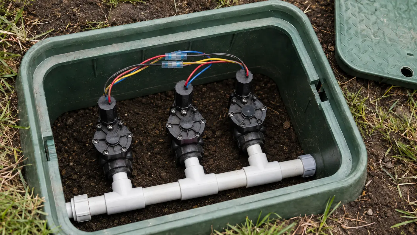
Do not confuse the coil with the whole field circuit
The same meter can read three different objects. Record where the leads are connected or the number has little diagnostic value.
| Test point | Result answers | It does not prove |
|---|---|---|
| Station-to-COM, valve active | Whether controller sends an AC command | That voltage reaches the valve |
| Across valve conductors, active | Voltage arriving under coil load | That the coil or pilot path works |
| Complete circuit, power off | Combined cable, splices, and coil resistance | Which individual item is bad |
| Disconnected coil, power off | The coil's own resistance | Valve diaphragm and ports are clear |
Use this boundary: Resistance ranges are model-specific. An ordinary-looking value is evidence, not a universal pass certificate.
A voltage, resistance, or click answers only one part of the circuit
These published Hunter examples show why a universal solenoid number is unsafe. Test the controller output, loaded field circuit, and disconnected coil as three separate boundaries.
| Published example | Documented value | What it can prove |
|---|---|---|
| Hunter station output | 24–28 VAC while the station is active | The controller is issuing a normal command at its terminals |
| Hunter Pro-C troubleshooting | Approximately 25–35 Ω for the isolated solenoid | This specific guidance supports a coil check after manual valve operation |
| Hunter X2 master-valve guidance | 20–30 Ω | A different documented range proves that 20–60 Ω is not a universal pass rule |
| Hunter 24 VAC valve solenoid | 350 mA inrush; 190 mA holding at 60 Hz | A short or high-resistance splice can affect behavior under load even when continuity exists |
| Controller versus valve voltage | Compare the same active command at both ends | A substantial field-side drop moves the fault to cable, common wire, or wet splice |
What the sample changes: Call the solenoid bad only when the hydraulic valve works, commanded voltage reaches the coil under load, and the disconnected coil fails its exact-model specification or a controlled substitute test.
Manufacturer troubleshooting pages were reviewed August 30, 2026. Values are kept with their original controller or valve context and are not blended into a made-up universal resistance range.Match the pattern before opening anything
| Possible cause | Best clue | First check |
|---|---|---|
| Open or shorted coil | No reliable activation and abnormal resistance | Test with controller power off |
| Corroded field splice | Intermittent operation after rain | Inspect both waterproof connectors |
| Low voltage under load | Hum or chatter without opening | Have voltage compared at controller and valve |
| Hydraulic valve fault | Solenoid activates but manual behavior is abnormal | Check pilot passages and diaphragm |
Read the system before replacing a part
Use the observation that most closely matches your yard. Each row changes the next test, so you do not spend an afternoon proving the wrong theory.
What it meansHydraulics work; missing output, an open conductor, bad splice, or open coil remains.
Do nextCompare active voltage at controller and valve before buying a coil.
What it meansThe coil may be energized with inadequate under-load voltage, be mismatched, or face a blocked pilot path.
Do nextMeasure voltage while energized and inspect wet splices.
What it meansA shorted coil, crossed copper, or damaged field cable may be drawing excess current.
Do nextDisconnect power and isolate coil from cable.
What it meansThe reading is describing an intermittent connection, not a stable coil.
Do nextReplace failed direct-bury splices and retest without moving the cable.
Four tests that narrow the fault
Stop as soon as one result gives you a clear boundary. The goal is not to perform every test; it is to eliminate whole groups of causes safely.
- 01
Pass the hydraulic test first
Open the valve by its manufacturer-approved manual control.
IF YES / NORMALNormal water flow allows electrical diagnosis of output, wire, splice, and solenoid.
IF NO / ABNORMALMissing water, flow control, ports, or diaphragm must be solved before judging the coil.
- 02
Measure active voltage at two locations
A trained person compares station-to-COM at the controller and voltage across the solenoid conductors while commanded on.
IF YES / NORMALSimilar normal voltage at the valve moves the boundary to coil or valve pilot action.
IF NO / ABNORMALA large drop in the field identifies cable, common, or splice resistance.
- 03
Separate complete circuit from isolated coil
With all power off, record resistance at the controller, then disconnect one coil lead and test the coil by itself.
IF YES / NORMALA plausible isolated coil plus abnormal full circuit points to wiring or splices.
IF NO / ABNORMALAn open or near-short isolated coil supports exact-model replacement.
- 04
Confirm with a repeatable operating test
After repair, run three short starts separated by shutdowns and observe opening, closing, sound, heat, and controller faults.
IF YES / NORMALThe valve opens and closes consistently without a fault.
IF NO / ABNORMALIntermittent voltage, pilot blockage, or mechanical valve trouble remains.
Numbers worth measuring
Measure under command and compare controller with valve; a no-load reading can hide resistance.
Not universal. Test the isolated coil and use the exact valve/controller documentation.
Can mean an open coil, conductor, or splice depending on where the leads are connected.
Common fixes that waste time
Different coils vary and a complete cable circuit can mask a marginal splice.
It can damage the meter and invalidate the result; isolate power first.
Movement does not prove adequate lift, correct voltage, or an open pilot passage.
How the evidence changes the repair
A valve worked from the bleed screw, hummed electrically, and was quoted for replacement.
- Controller output was 26.1 VAC during the run.
- Only 17.4 VAC reached the energized coil.
- The isolated coil read within the exact model range; a wet splice showed blackened copper.
The under-load voltage boundary contradicted the replacement quote. A new waterproof splice restored full voltage and repeatable valve opening; the coil and valve stayed in service.
How to confirm the repair actually held
A single successful start can hide an intermittent splice, sticky valve, remaining leak, or scheduling problem. Recreate the original conditions before calling the job finished.
Pass: The valve opens every time without hum, chatter, or fault message.
If not: An intermittent splice, coil, output, or pilot path remains.
Pass: Controller and valve readings are similar under command.
If not: Cable or splice resistance still consumes voltage.
Pass: Connections remain dry, secure, and unchanged when gently moved with power off.
If not: The field repair is mechanically or environmentally marginal.
Check these in order
- 01
Confirm the valve can pass water
Operate the valve by its approved manual method. If it cannot open manually, do not blame the coil until supply, flow control, passages, and diaphragm are checked.
- 02
Listen during a controller command
Silence can mean no electrical signal, an open circuit, or a failed coil. A click or hum means the coil is energized but does not prove the valve opened.
- 03
Inspect the two field splices
Turn controller power off and look for moisture, corrosion, loose copper, or indoor connectors. A splice problem can mimic a failed solenoid and is often cheaper to correct.
- 04
Use a power-off circuit test
A trained person can compare resistance with the manufacturer's specifications and with known-good matched zones. Disconnect power before resistance measurements.
- 05
Replace only with an exact match
Match voltage, threads, plunger, and valve family. Photograph wiring, use direct-burial waterproof connectors, and test a short cycle before closing the box.
- The controller output or field cable requires live testing.
- The coil repeatedly overheats or trips protection.
- A replacement solenoid does not correct the symptom.
What homeowners ask about this symptom
Can a sprinkler solenoid click and still be bad?
Yes. It can move enough to click but remain weak, intermittent, mismatched, or unable to relieve valve pressure. Check the valve and circuit rather than using sound as the only test.
Are all sprinkler solenoids interchangeable?
No. Voltage, thread, plunger design, and hydraulic passages vary by valve family. Use the exact manufacturer-compatible part.
Sources and review notes
General maintenance logic is checked against EPA WaterSense outdoor irrigation guidance. Product controls and disassembly steps vary by model; use the current manufacturer manual for your exact valve, controller, or sprinkler head.