Use gravity drainage only when the system was designed with correctly located manual or automatic drains and the pipe can actually empty toward them. Blowout can remove water from trapped low points, but excessive air pressure or volume can damage components and create projectiles. If you cannot identify the design, a professional winterization is safer than guessing.
Choose by trapped-water geometry, not by habit
A label such as “manual drain system” is no longer reliable if later landscaping or pipe changes created new low points.
| System evidence | Method implication | Stop condition |
|---|---|---|
| Documented drains at every low point | Gravity drain may be intended | Any dip/check valve/addition lacks a downhill path |
| Automatic drains are documented | Pressure release may drain designed sections | Location or contamination protection is unknown |
| Dedicated blowout fitting and limits | Professional compressed-air clearing is plausible | Pipe material, CFM, pressure, or isolation is unknown |
| Mixed/modified/unknown layout | No method is proven complete | Have system identified before connecting air |
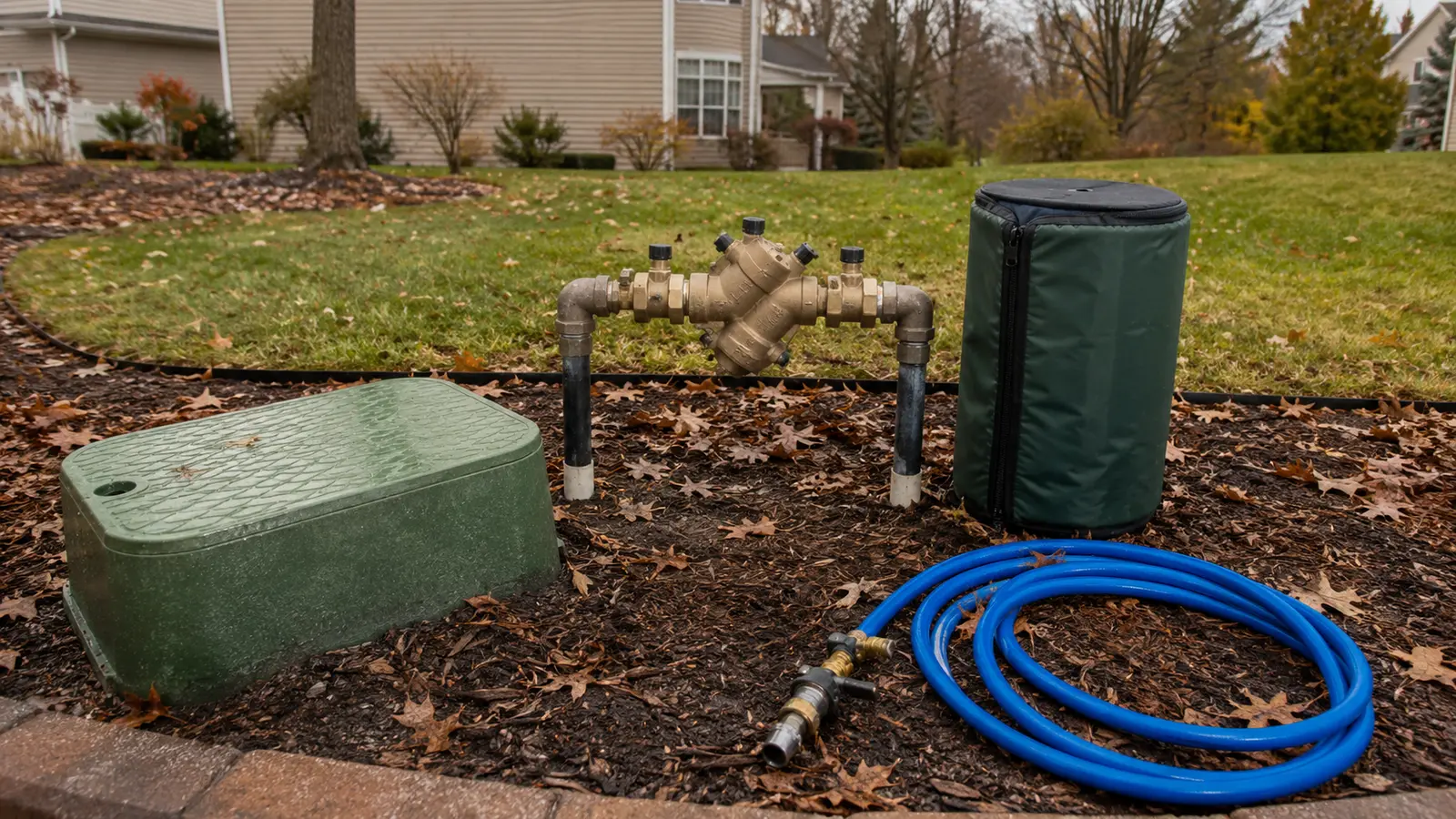
Use this boundary: Never send compressed air through a backflow assembly. Isolate and protect each component according to its manufacturer and local requirements.
The weakest documented component sets the blowout limit
Pressure alone does not clear a system; air volume moves the water. At the same time, a component that tolerates water pressure may not tolerate prolonged high-velocity air.
| Evidence | Published limit or condition | Decision it changes |
|---|---|---|
| Rain Bird homeowner blowout guide | 10–25 CFM air volume; do not exceed 50 PSI | A small shop compressor may show pressure yet lack sustained volume |
| Rain Bird DV valve instructions | Compressed-air source should not exceed 60 PSI | Exact component literature can impose a separate ceiling |
| Rain Bird legacy flow meter | Do not connect air upstream for prolonged blowout | Some inline sensors need draining or bypass/isolation instead |
| Manual/automatic drain layout | Every trapped low point needs a downhill drain path | Later grading, check valves, and pipe dips can defeat gravity |
| Backflow assembly | Do not use it as the compressed-air path | Isolate and winterize the assembly by its own instructions |
What the sample changes: Choose the method only after mapping drain points, check valves, sensors, backflow hardware, pipe material, and the approved air connection.
Limits were taken from manufacturer documents, not generalized from compressor advertising. When two components publish different limits, follow the lower applicable limit and the exact system procedure.Match the pattern before opening anything
| Possible cause | Best clue | First check |
|---|---|---|
| Manual gravity-drain design | Documented low-point drain valves are present | Confirm each zone slopes to an accessible drain |
| Automatic-drain design | Rated drains open when line pressure falls | Verify their location and that trapped sections still have an exit |
| Blowout-dependent layout | Low points cannot drain by gravity | Use the installer-specified connection and limits |
| Unknown or mixed system | Additions, slopes, and valves do not match one method | Stop and have the layout identified |
Read the system before replacing a part
Use the observation that most closely matches your yard. Each row changes the next test, so you do not spend an afternoon proving the wrong theory.
What it meansGravity drainage may be the intended method.
Do nextConfirm that later additions and check valves did not create trapped sections.
What it meansGravity may leave water in low pockets below the drain outlet.
Do nextHave the installed winterization method verified.
What it meansCompressed-air clearing was contemplated by the installer.
Do nextUse trained service and respect both pressure and flow limits.
What it meansIts purpose and safe isolation path are unknown.
Do nextDo not attach a compressor based on appearance alone.
Four tests that narrow the fault
Stop as soon as one result gives you a clear boundary. The goal is not to perform every test; it is to eliminate whole groups of causes safely.
- 01
Trace elevation to every drain
On a sketch, connect each zone's high and low points to its documented drain outlet.
IF YES / NORMALEvery water pocket has a downhill path.
IF NO / ABNORMALA dip, check valve, or uphill run can retain water.
- 02
Verify the blowout connection
Match the connection, isolation sequence, pipe material, and limits to installer or manufacturer documentation.
IF YES / NORMALThe method is specific to this system.
IF NO / ABNORMALAn improvised port or unknown limit is a professional stop point.
- 03
Check pressure and sustained air separately
Use regulated equipment specifications; never infer useful airflow from tank PSI alone.
IF YES / NORMALBoth stay inside system limits while providing the required clearing flow.
IF NO / ABNORMALHigh pressure can damage hardware; inadequate flow can leave water trapped.
- 04
Audit every cavity after the zones
Account for backflow hardware, pumps, filters, manifolds, drain bodies, and later additions.
IF YES / NORMALThe completion record covers more than visible sprinkler heads.
IF NO / ABNORMALOne forgotten cavity can freeze even if the zones emitted air.
Common fixes that waste time
Air pressure can damage fittings and turn debris or heads into projectiles.
Remote low points and device cavities may still contain water.
They can introduce leakage or contamination concerns and still miss trapped geometry.
How the evidence changes the repair
A sloped property had manual drains at two valve boxes, but a later patio reroute dipped below both outlets.
- Original zones drained visibly by gravity.
- The added lateral rose over a retaining edge after its hidden low point.
- No as-built update documented the new geometry.
The label 'manual drain system' was no longer enough. Mapping elevation exposed one trapped section that required system-specific winterization rather than blindly opening the original drains.
How to confirm the repair actually held
A single successful start can hide an intermittent splice, sticky valve, remaining leak, or scheduling problem. Recreate the original conditions before calling the job finished.
Pass: Every zone, low point, and exposed device is accounted for.
If not: The method did not cover the whole system.
Pass: They reached their intended final state without seepage from the live supply.
If not: A shutoff or drain may be passing water.
Pass: The work is reproducible next season.
If not: Unknown steps will return at spring startup.
Check these in order
- 01
Find evidence of the installed design
Look for as-built plans, labeled low-point drains, automatic-drain fittings, and a dedicated blowout connection. A nearby threaded port is not automatically a safe compressor connection.
- 02
Map water that gravity cannot remove
Note uphill runs, pipe dips, check valves, backflow hardware, manifolds, and later additions. Water below a drain outlet or behind a closed device remains trapped.
- 03
Separate pressure from air volume
A small compressor may show pressure yet lack the sustained air volume to clear a zone; excess pressure can damage pipe and heads. Both limits must match the system material and installer guidance.
- 04
Protect people before hardware
Never stand over heads, valves, or fittings during blowout. Wear eye protection, keep others clear, and stop if a component chatters, heats, or ejects debris.
- 05
Use a completion check
Document every zone and exposed component addressed. Water stopping at one head does not prove every low point, backflow cavity, pump, or filter housing is empty.
- No documented method or dedicated blowout connection can be found.
- The system includes a pump, RPZ/PVB device, filter housing, or mixed pipe materials.
- You do not have compressor flow controls, safe connection hardware, and exact pressure limits.
What homeowners ask about this symptom
Is draining sprinklers as good as blowing them out?
It can be when the system was intentionally designed to drain completely by gravity. It is not equivalent when low points, check valves, or later modifications trap water.
Can I blow out sprinklers with a small home compressor?
Tank pressure alone does not answer that. Safe clearing depends on controlled pressure, sustained air volume, pipe material, zone size, connection design, and manufacturer guidance.
Sources and review notes
General maintenance logic is checked against EPA WaterSense outdoor irrigation guidance. Product controls and disassembly steps vary by model; use the current manufacturer manual for your exact valve, controller, or sprinkler head.
Published and last reviewed: August 30, 2026